Starting Air Valve Timing Diagram Piston Marineengine
Timing valve diagrams Valve air starting man engine balanced Valve timing diagram for the engine used. the intake and exhaust valve
Actual Valve Timing Diagrams of 2 Stroke And 4 Stroke Marine Diesel Engines
Valve timing diagram: for 2-stroke, 4-stroke engines, importance. Valve timing diagram pdf Timing stroke diagram engine valve two four actual theoretical port petrol cycle engines diesel combustion exhaust intake steps working fuel
Timing diagrams
[diagram] petrol engine timing valve schematic diagramsAir start valve explained Timing stroke valve diesel marine actual diagram diagrams engines engine four twoValve timing diagram.
Watch: air starting valve of main engineValve timing diagram of four stroke si engine – low speed and high Piston marineengineAir starting valve.
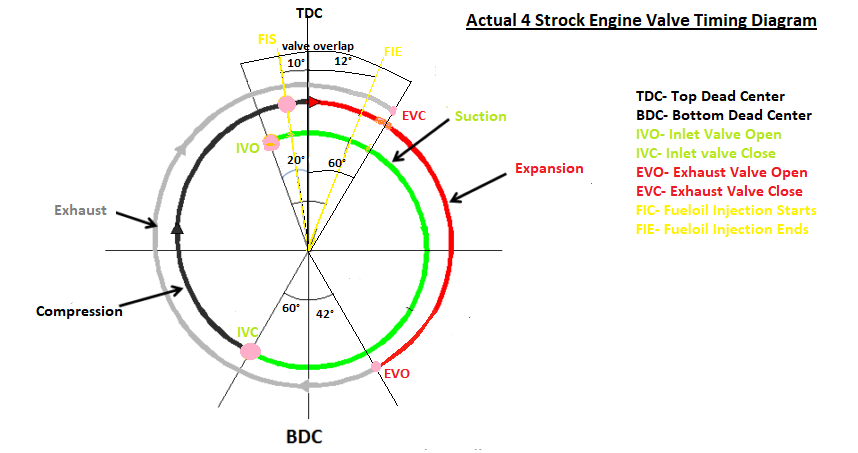
The valve timing diagram of four-stroke si engine.
Valve timing diagramAir starting valve-man b&w engine Valve timing diagram of two stroke and four stroke engines: theoreticalAir starting valve|working of air starting valve| type of air starting.
Valve timing diagramTheory of engine & starting arrangement Valve timing diagramsValve timing diagram of two stroke and four stroke engine.

Starting air admittance valves explained
Valve timing diagram of two stroke and four stroke engines: theoreticalStarting air valve Timing engine stroke affects briggs stratton inlet carbiketech combustionWatch: air starting valve of main engine.
Stroke timing valve diesel marine actual diagram diagrams engines engineValve timing diagram Air starting line diagram safety easy simple explosion safeties understandingValve stroke timing diagram engine actual four theoretical two cam engines petrol tdc piston exhaust cylinder fuel opening practical bdc.

Air starting valves valve admittance diagram marine explained construction ships used
Timing intake openings vvtAir valve starting man engine fir Valve timing diagram of two stroke and four stroke engineValve timing diagram of 2 stroke diesel engine [ci engine] actual port.
Actual valve timing diagrams of 2 stroke and 4 stroke marine diesel enginesValve timing diagram Timing valve diagram drawValve timing stroke operation.

Valve piston
Actual valve timing diagrams of 2 stroke and 4 stroke marine diesel enginesValve timing diagrams Air start valve explainedWhat is valve timing & how it affects engine performance?-carbiketech.
How to draw valve timing diagramAutomatic master air start valve sulzer with a simple diagram Valve stroke diagram engine diesel timing four two injection fuel actual exhaust advance tdc piston mechanicalbooster inlet mesinMain engine starting air valve testing: important tips for engineers.

5 brilliant starting air line safeties to avoid an explosion
Valve air start automatic diagram master sulzer simple engine stop shows .
.

![Valve Timing Diagram of 2 Stroke Diesel Engine [CI engine] Actual Port](https://i.ytimg.com/vi/JR6tGPIRap4/maxresdefault.jpg)
Valve Timing Diagram of 2 Stroke Diesel Engine [CI engine] Actual Port

VALVE TIMING DIAGRAM OF TWO STROKE AND FOUR STROKE ENGINES: THEORETICAL

VALVE TIMING DIAGRAM - YouTube

The valve timing diagram of four-stroke SI engine. | Download

VALVE TIMING DIAGRAM OF TWO STROKE AND FOUR STROKE ENGINES: THEORETICAL

5 Brilliant starting air line safeties to avoid an Explosion